Mechanical design & aerodynamics study
Wind Turbine Project — Geometry, Blade Optimization & CFD
A 1:100 scale turbine modeled in Solidworks by Anirudh Bhat — from tower, nacelle and hub geometry through eighteen blade variations, validated in CFD with FEA in progress.
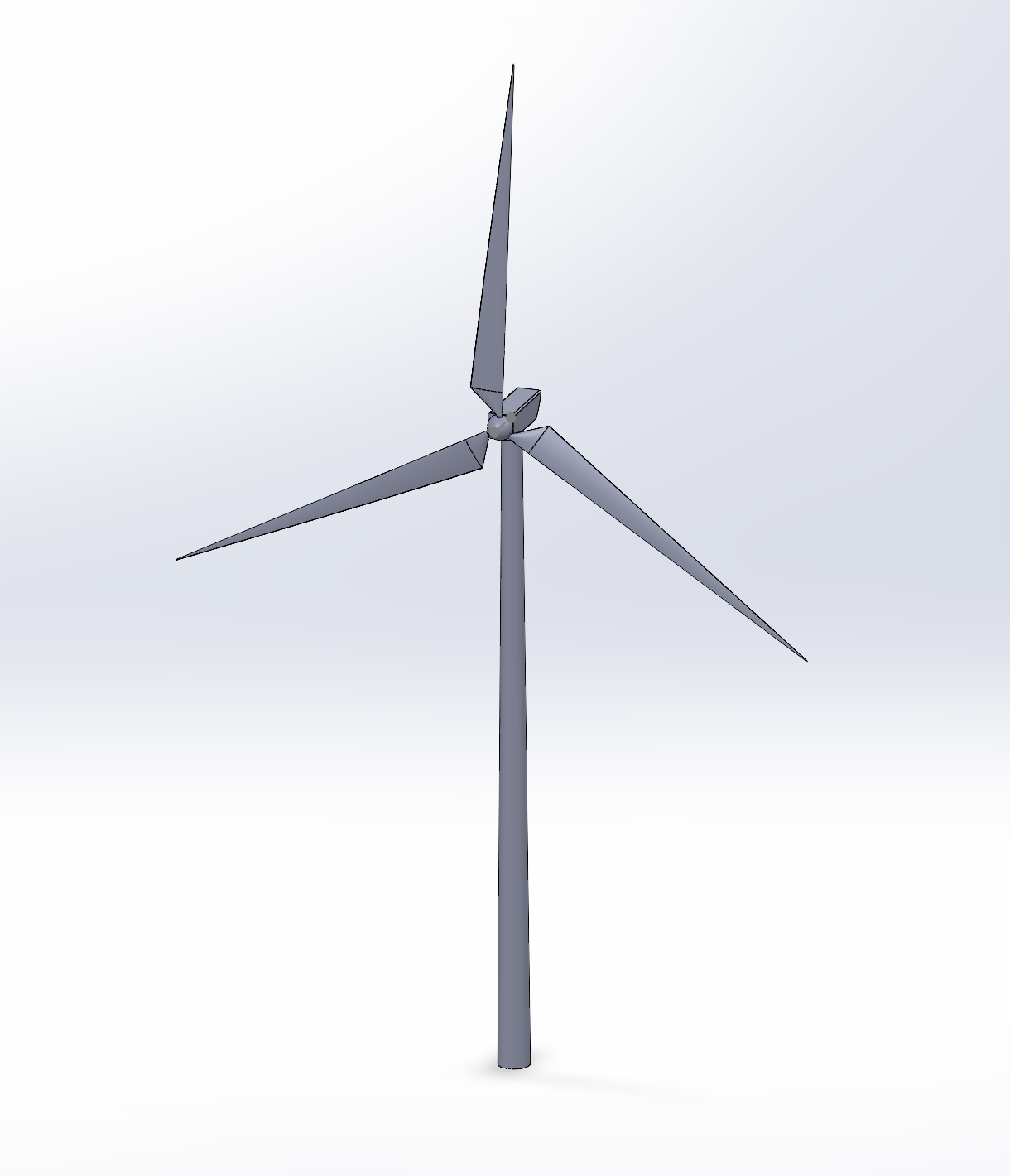
Component 01
Tower
A tapered mast revolved about the origin, carrying the nacelle at hub height and drafted to the 1:100 model scale.

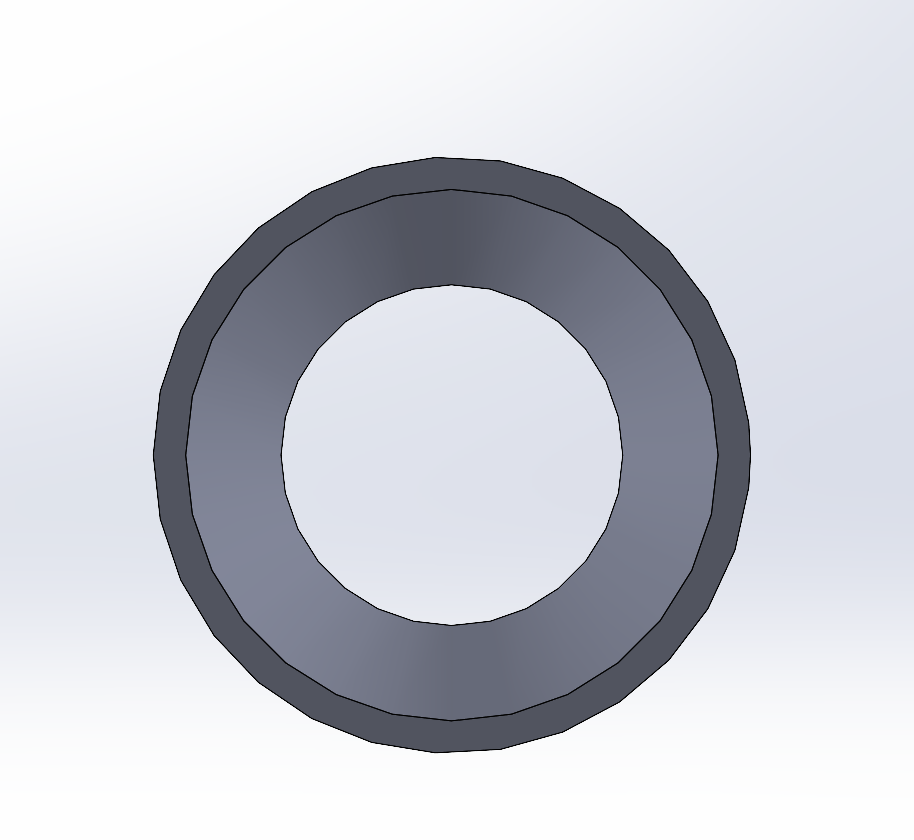
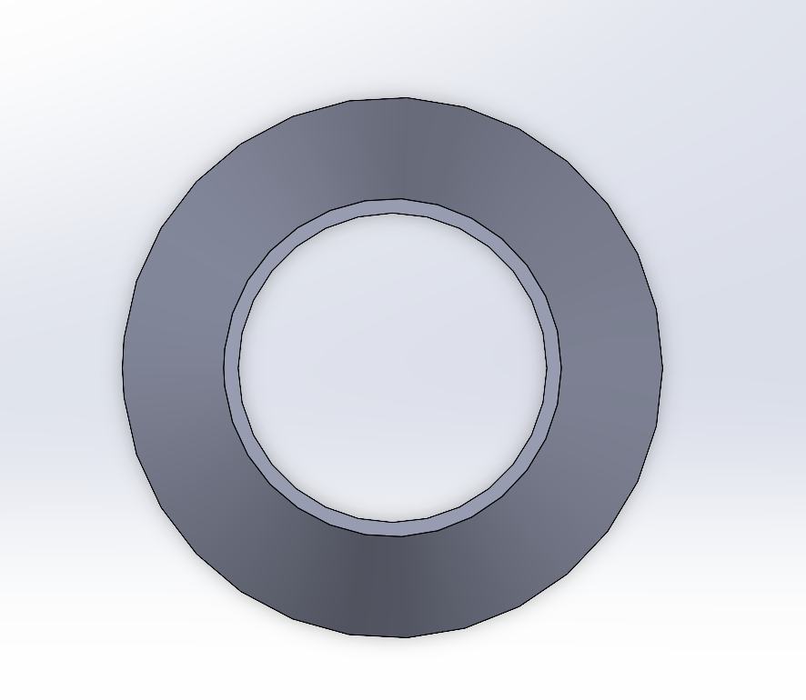
Component 02
Nacelle
A tapered housing block cut for the main shaft and filleted at the leading edges to seat cleanly against the hub.
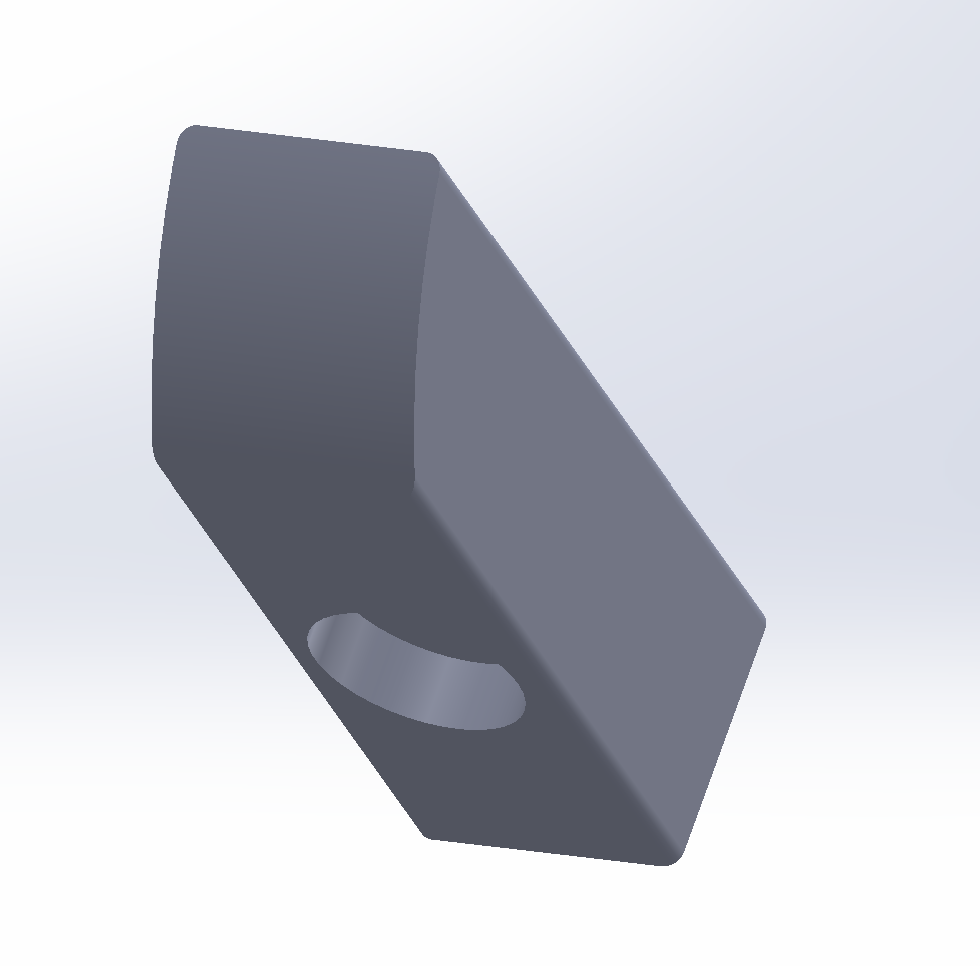
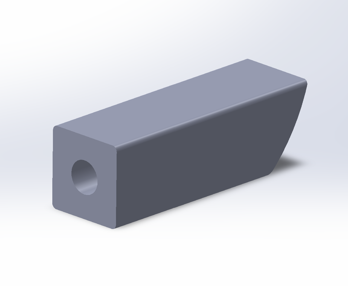
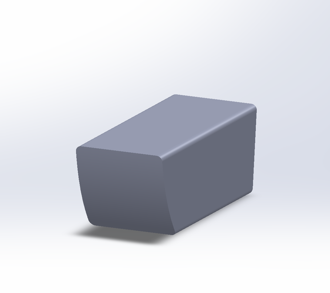
Component 03
Hub
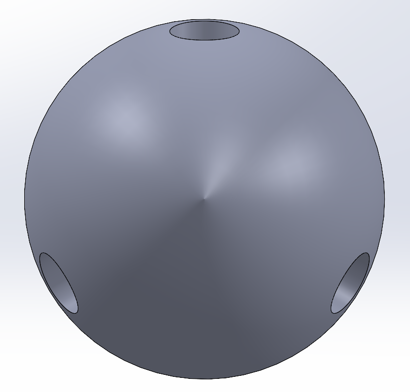
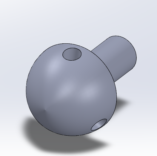
A spherical hub with three blade-root bores and a filleted nose cone, joining the rotor to the nacelle shaft.
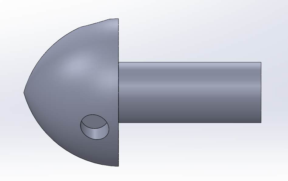
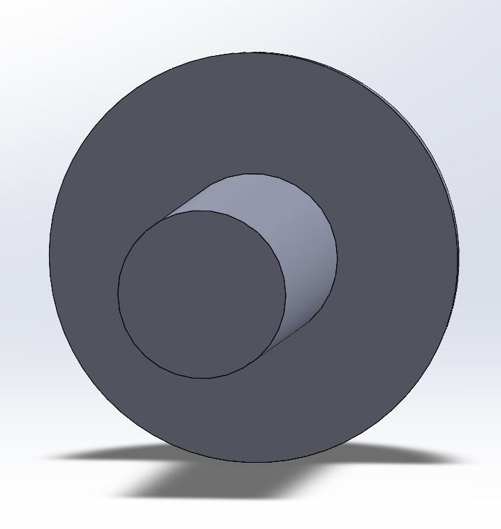
Component 04 · Wing portfolio
Two camber families
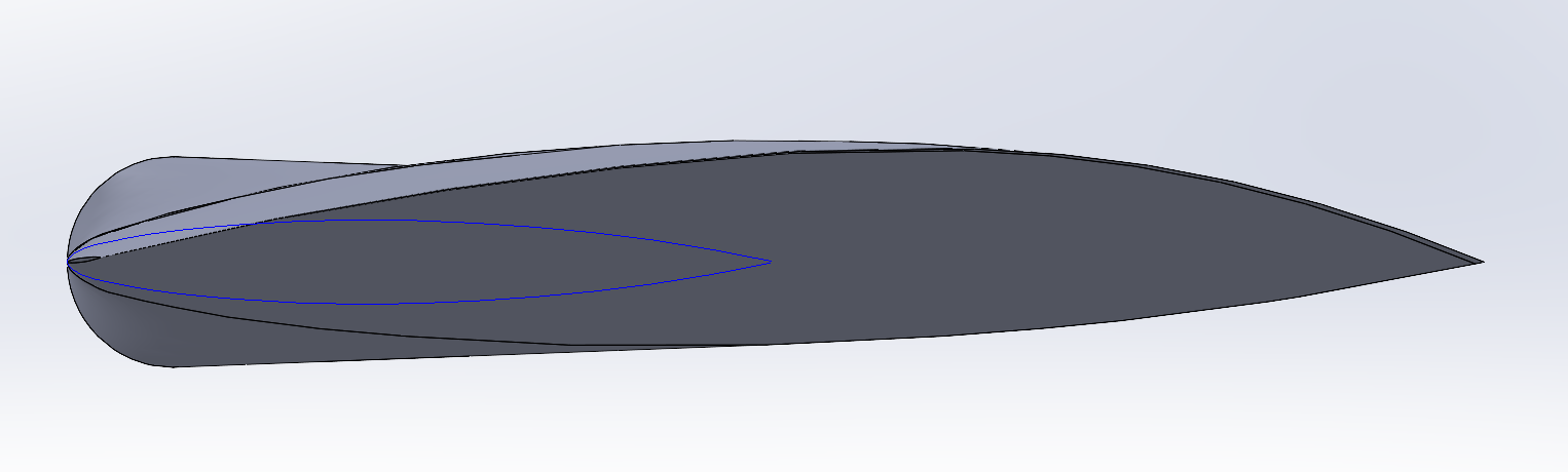
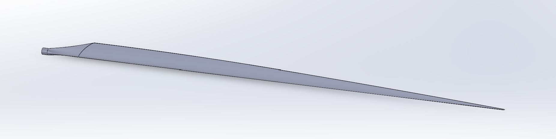
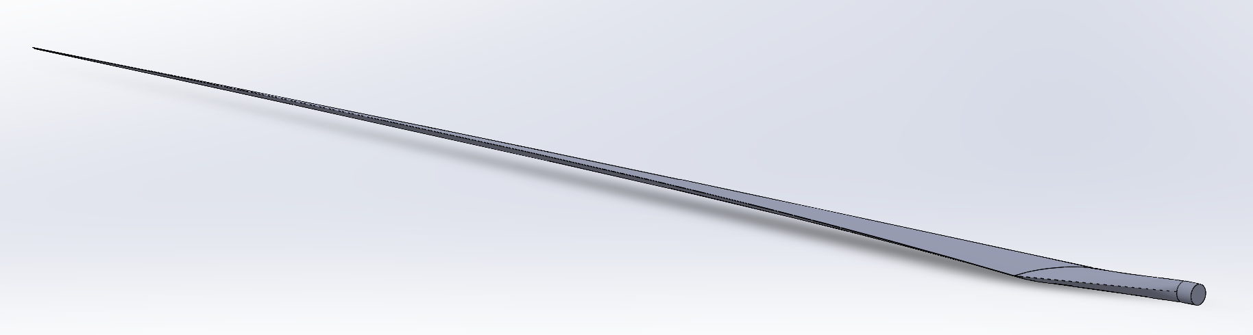
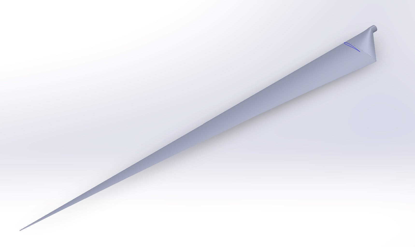
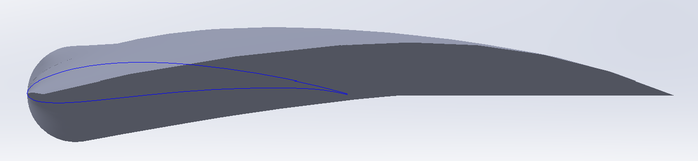
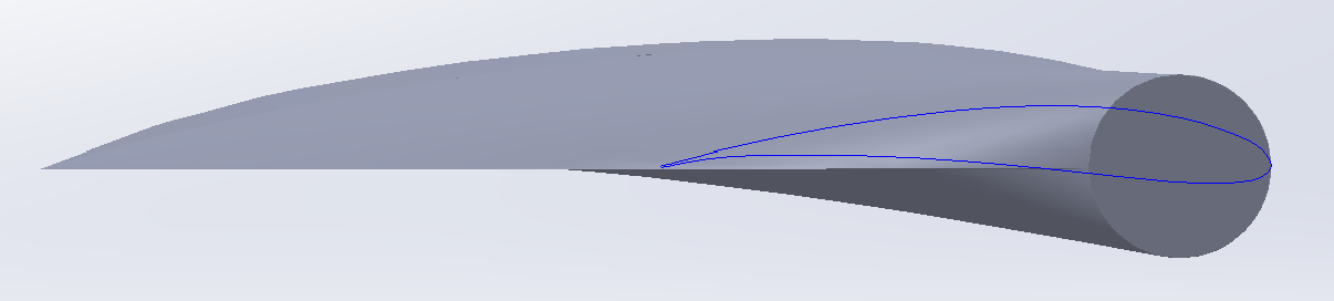
The blade was built twice — once on the symmetric NACA 0012 section and once on the cambered NACA 4412 — so the airfoil could be compared with every other variable held identical.
General photoshoot · NACA 0012
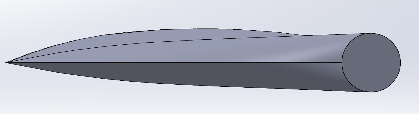
General photoshoot · NACA 4412



Study 05
Taper × Twist matrix
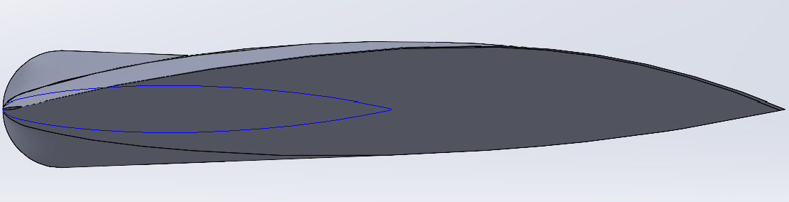
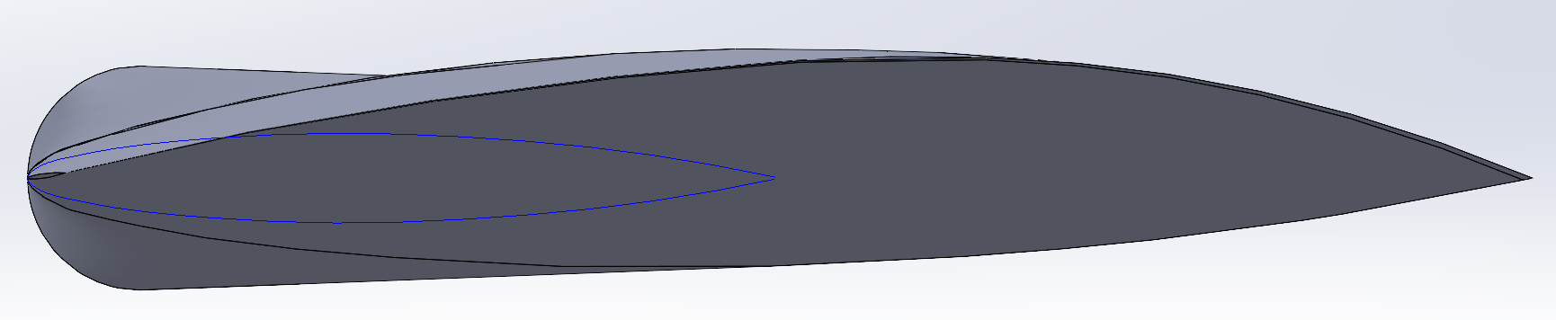
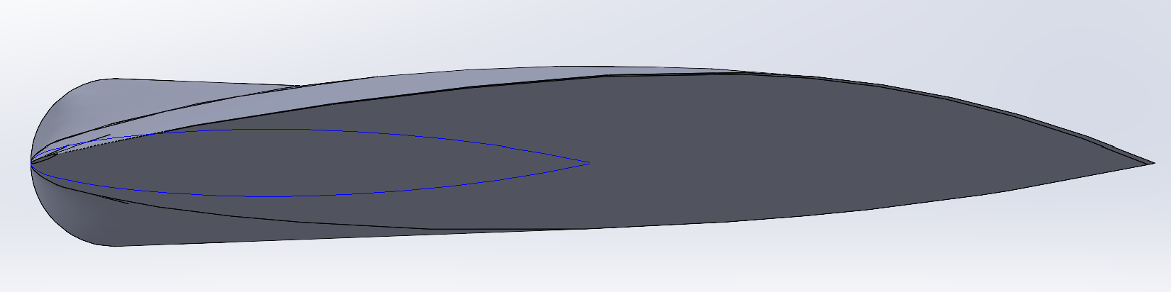

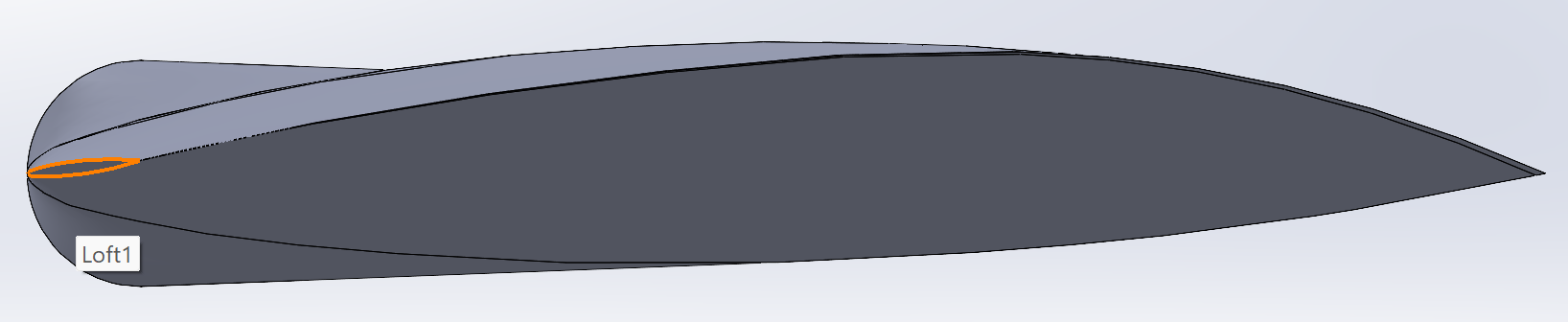

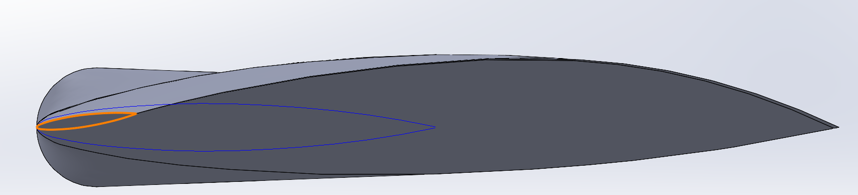
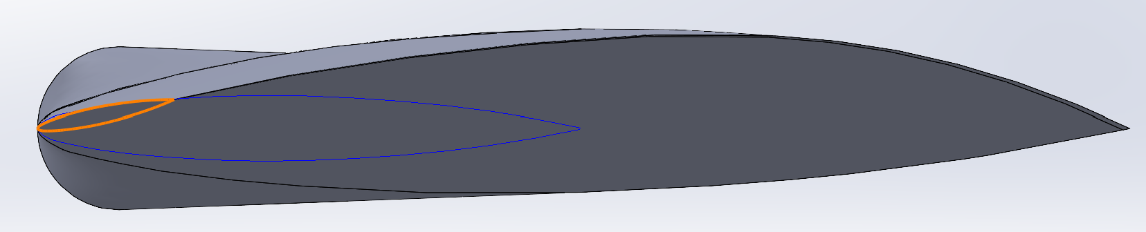

Note — during preliminary airfoil and taper testing the blade twist direction was modeled opposite to the intended convention. Because the orientation was applied consistently across those comparative cases, the results were retained for relative comparison and the limitation documented. All 8°, 12° and 16° mid-taper configurations were regenerated with the intended twist direction before final aerodynamic selection.
Process 06 · Wing creation
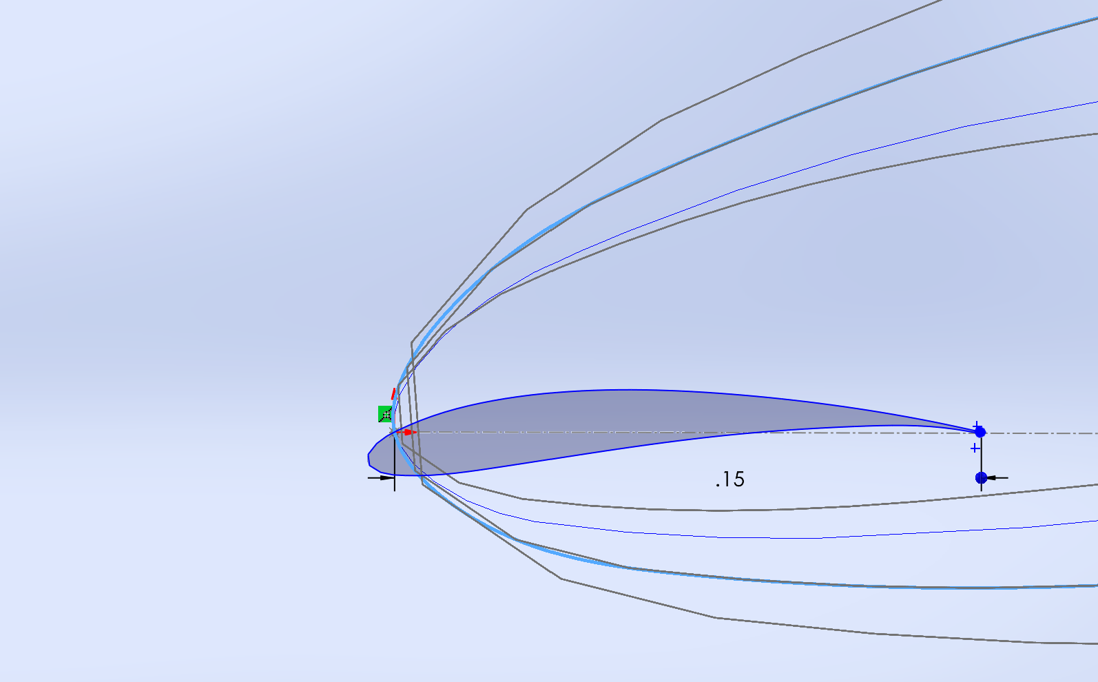
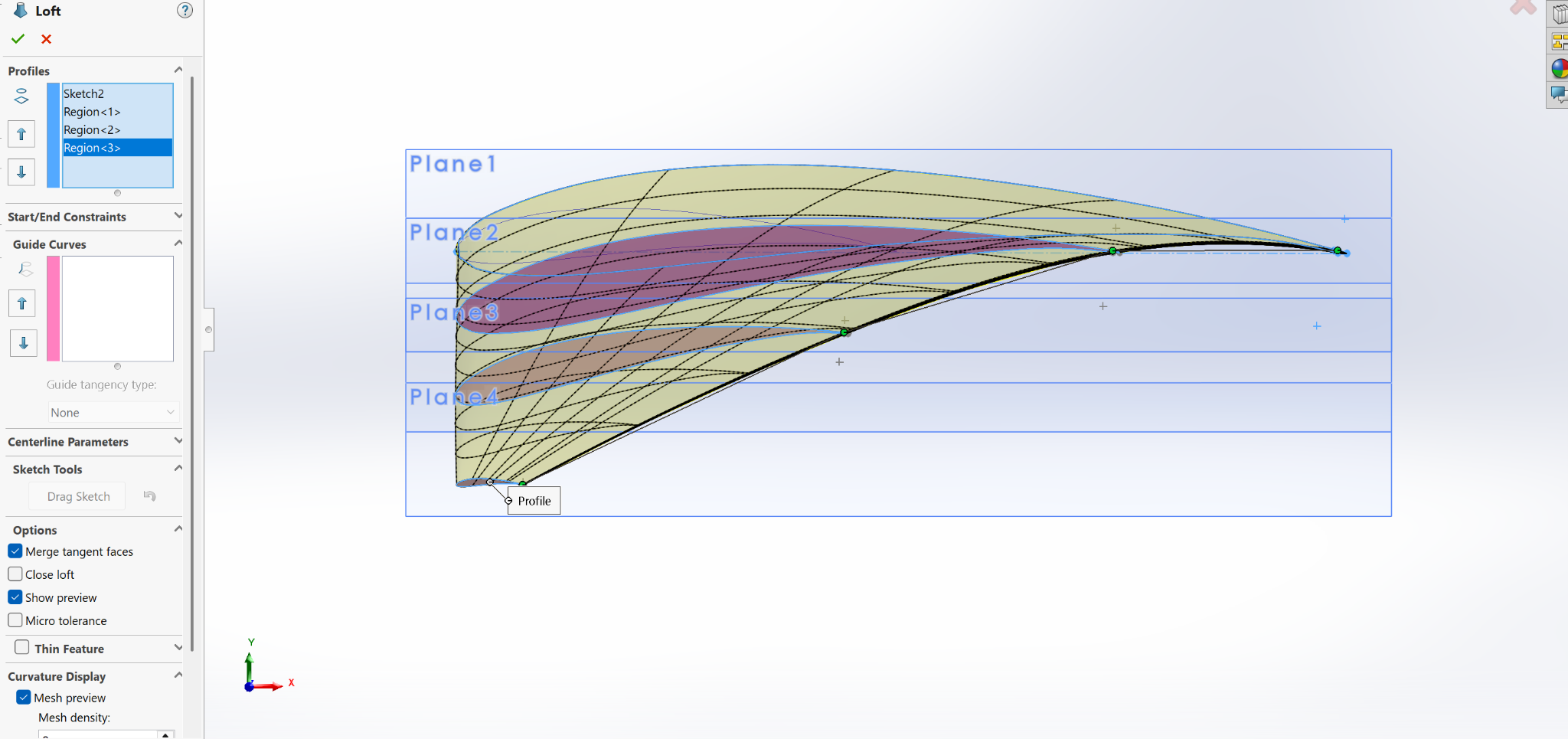
Sketch, offset planes, loft
| Reference plane | Offset x | High taper | Mid taper | Low taper |
|---|---|---|---|---|
| Plane 1 (Root Datum) | 0.00 in | 2.00 in | 2.00 in | 2.00 in |
| Plane 2 (Mid-Span 1) | 6.00 in | 1.43 in | 1.46 in | 1.49 in |
| Plane 3 (Mid-Span 2) | 13.00 in | 0.76 in | 0.82 in | 0.88 in |
| Plane 4 (Tip Datum) | 20.40 in | 0.05 in | 0.15 in | 0.25 in |
Linear interpolation: Chord(x) = Chord_root + (x / L_total) · (Chord_tip − Chord_root), with Chord_root = 2.00 in and L_total = 20.40 in.
| Reference plane | Offset x | Config 1 | Config 2 | Config 3 |
|---|---|---|---|---|
| Plane 1 (Root Datum) | 0.00 in | 0° | 0° | 0° |
| Plane 2 (Mid-Span 1) | 6.00 in | 6° | 6° | 6° |
| Plane 3 (Mid-Span 2) | 13.00 in | 10° | 10° | 10° |
| Plane 4 (Tip Datum) | 20.40 in | 8° | 12° | 16° |
Low pitch / high speed
Optimized for high tip-speed ratios. Reduces pitch at high rotational speeds to prevent premature boundary layer separation and high-speed fluid stall.
Baseline optimal
Aligns with maximum aerodynamic efficiency at optimal tip-speed ratio, capturing peak lift-to-drag efficiency prior to boundary layer detachment.
High pitch / low speed
Increases local attack angle for low speed sweeps to improve low-speed torque generation and startup responsiveness.
Analysis 07 · CFD & FEA
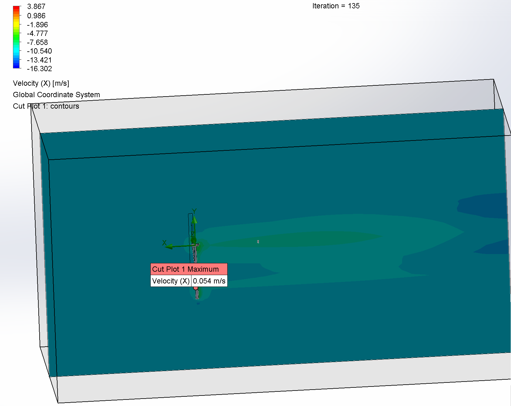
Testing the assembly
Testing order
- Compare NACA 4412 vs. NACA 0012, everything else identical.
- Keep the better airfoil and compare taper ratios.
- Keep the best taper and compare twist angles.
- Keep the best twist and compare pitch angles.
Domain setup
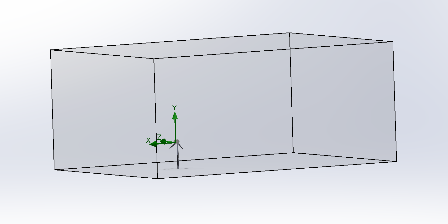
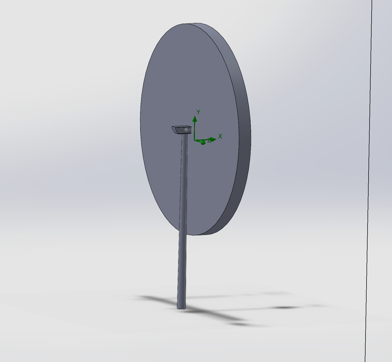
The turbine sits in a rectangular computational domain, with a cylindrical rotating region treated as a body of air enclosing the hub and blades.
FEA · in progress
The winning blade configurations are being re-run in three materials: E-glass fiberglass, carbon fiber reinforced polymer (CFRP) and Elium resin.